
Frequently Asked Questions

Thunder F A Q's
Thunders Q & A Section
 Answer: Daily.
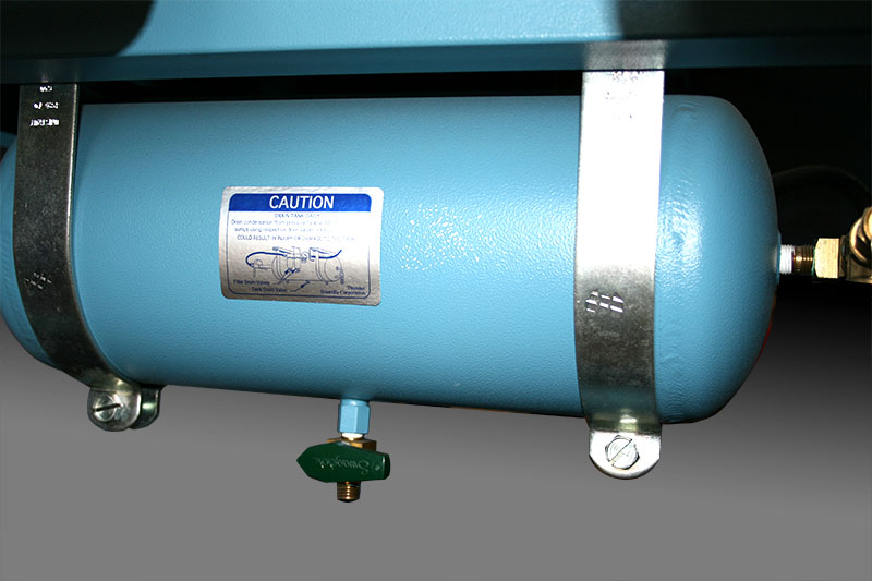
After you are finished doing your calibrations for the day, shut down both the generator and the air box. Locate the air supply line at the rear of the system and turn the air supply valve handle to the off position. Drain condensation from the air pressure tank using the drain valve located on the bottom of the tank; open the valve all the way. Also drain condensation from the inline air filter sumps using the drain valve on the bottom of each sump. Be sure to close all drain valves before starting up the air box or introducing supply air through the sumps/pressure tank from any other source.
This maintenance procedure is in the 2500 system manual in Section 4.3.4 Mobile Pneumatic Cart.
Answer: Yes.
Thunder recommends you calibrate your system yearly.
You can send your system back to the factory for calibration. Ask about our special transportation shipping cases to ship your generators back to Thunder.
You can calibrate your own system, provided you have pressure and temperature standards with sufficiently small uncertainties to adequately support the generator’s published specifications.
Additionally, we can provide field calibration service at your facility for three of our generator models: the 1200, 2500, and the 2900.
Answer: Yes.
An alternate air source, such as your facility’s ‘house air,’ can be used in place of the pneumatic cart so long as it meets the requirements below.
A clean, oil free instrument air supply operating at 165 psiG and 50 L/m is required. The air supply should be filtered to a particle size of 0.5 microns or smaller, a hydrocarbon content of 1 PPM or less, with a dew point of 15 °C or lower. Regulated supply pressure other than the recommended maximum level of 175 psiG is acceptable but may limit the lowest humidity obtainable from the generator; adjustment of the 2500’s internal pressure regulator (REG) may be required.
Answer: Yes.
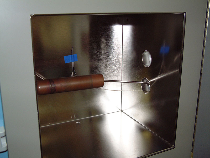
Using a manifold is helpful, as it speeds the acclimation time of most test instruments. With the manifold installed, and the test instrument suspended inside the manifold, conditioned air enters the chamber through the manifold and flows directly over the test instrument on its way into the chamber. This creates a more streamlined flow, with the test instrument protected from much of the eddy current activity. This can significantly reduce the settling time at each test point, thus reducing the total time required to complete a calibration event.
Answer: Yes.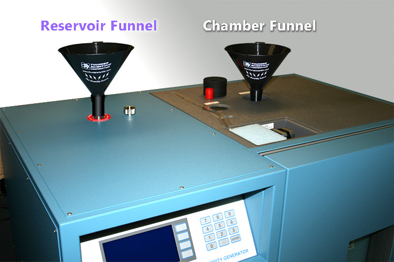
When looking at the front of the 2500 system, the chamber jacket fluid fill port is located on the top right side of the unit; the right hand top panel must be removed to access that fill port. The fluid used in the chamber jacket is 50-70% propylene glycol based antifreeze rated at -100 °F (-73.3 °C), or equivalent. Refer to TSD-0207 for chamber jacket filling instructions.
The reservoir fill port is located on the top left side of the 2500 system; this is visible without removing any panels. The reservoir fill port cap will need to be removed to access the fill tube. The reservoir is designed to be operated with distilled water only (not deionized). Refer to Section 3.2.9 of the 2500 operation and maintenance manual for the reservoir filling instructions.
The difference between the two is.
Double distilled has gone through the process twice. Single-distilled water will work fine in the generator. The goal with distilled water is to remove the minerals so that we don't leave deposits inside the generator as the water transitions from liquid to gas. We strongly recommend using plain distilled water that you can get at Wal-Mart, Walgreens, or the local store.
Never use deionized water because it is very aggressive to the stainless-steel components in our systems. This type of water will cause contamination and damage the pre-sat fill solenoid, as well as the Pre-Saturator components.
 Answer: Yes.
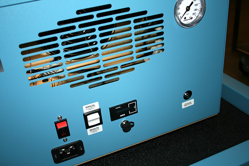
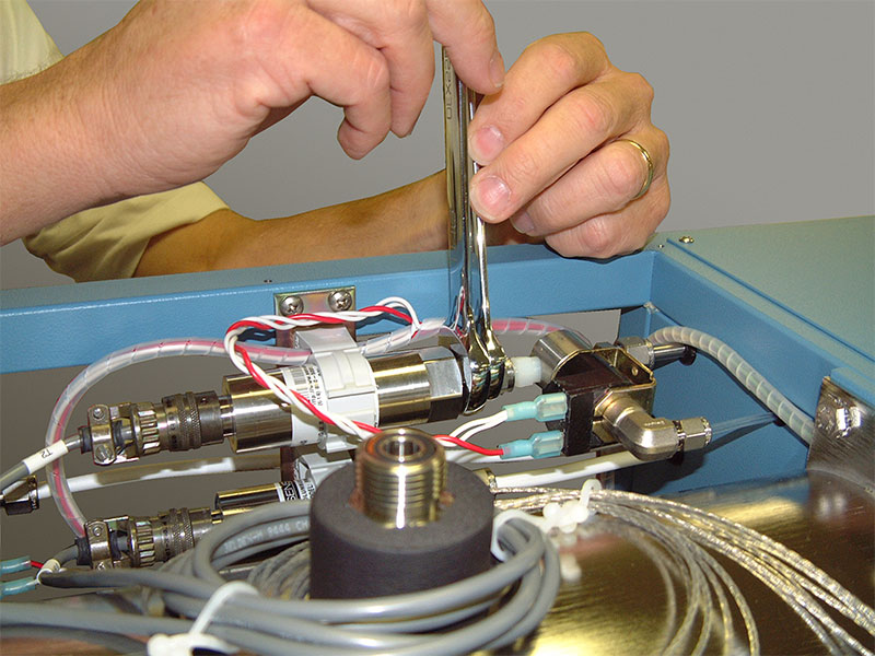
On the power input end of the air box is a pressure gauge. Straight down from that is the pressure regulator adjustment shaft. Power up the air box. During no-flow conditions (2500 generator not generating), turn the 9/32” (7 mm) adjustment shaft clockwise to increase pressure and counterclockwise to decrease pressure to achieve 165 psiG. Set 2500 to Generate mode. Monitor the air box pressure gauge over the next 30 minutes to an hour while the air box warms to its working temperature. Make minor adjustments to the regulator as needed to achieve the correct working pressure of 160 psiG.
Note: Pressures higher than 165 psiG should be avoided. Higher pressures will be indicated by the “popping off” of the compressor safety valve.
 Answer:
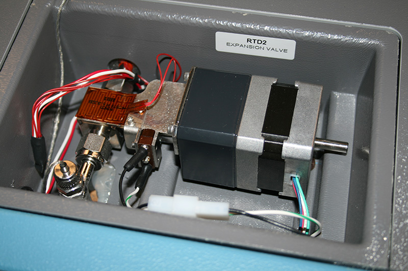
The error code ‘1’ indicates the expansion valve is not closing. To troubleshoot this error, first ensure the electrical connector to the valve is firmly seated. Check to see if the limit switch is loose or bent.
Use
TSD-0216 for further help and clarification.
 Answer:
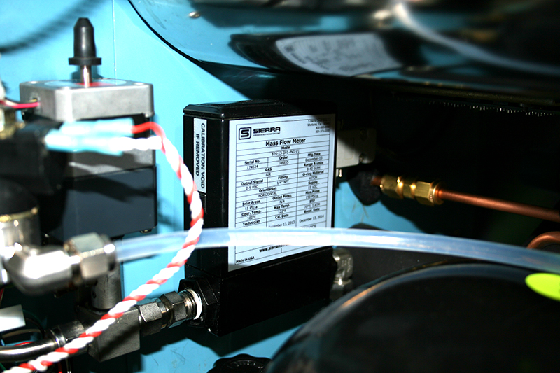
The flow of air through the generator is displayed relative to mass. The mass flow control system utilizes a thermal type Mass Flow Transducer. Mass flow rates through the generator are user-adjustable from 2 to 20 L/min through the main keyboard. Open the user manual for the Model 2500, then refer to Section 1 under number 1.5.4.2 Mass Flow Transducer (T1) for more information on the mass flow transducer.
 Answer:
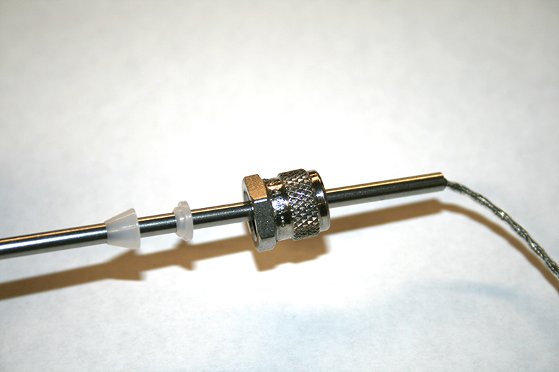
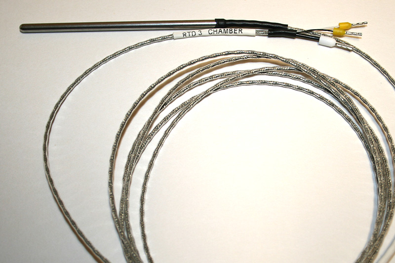
Temperature probes RTD0, RTD1 and RTD2 require the use of nylon ferrules for proper operation. First insert the tip of the RTD into the top of the knurled nut, then slide the rear ferrule (part number N204-1) onto the RTD with the step side facing away from the nut. Next, slide the front ferrule (part number N203-1) onto the RTD with the cone side facing away from the nut. Insert the probe into the probe housing leaving 1/4" (6.35 mm) of the probe’s shaft exposed, then tighten up just past finger tight.
For replacement ferrules see our parts page and look for part numbers (N203-1/N204-1).
 Answer: Yes.
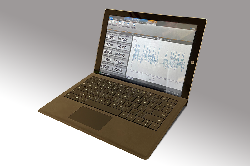
Desktop 2900 ControLog
The 2900 does have a new command interface to support our new Desktop 2900 ControLog but it also supports the legacy 2500 commands. Any Model 2900 Humidity Generator running HW version 29.0.10.0 or newer will support the legacy 2500 command structure (refer to 2500 system manual for more information) with the following exceptions:
- Only the following serial settings are supported with the 2900.
- Baud Rate = 57600
- Data Bits = 8
- Parity = None
- Stop Bits = One
- Handshake = None
- RTS Enable = true
- DTR Enable = false
- The 2900 only supports %RH@PcTc via the %RH data item and does not support %RH@Pc. Any legacy 2500 command that sets or returns %RH@Pc will instead set or return the %RH data item (same as %RH@PcTc)
- The 2900 error codes do not map nor are 2500 error codes applicable to the 2900. The ?ER command will return 0 if there are no 2900 errors and will return 32767 if any 2900 error is currently issued. Refer to the 2900’s HMI display for details on any issued 2900 error.
- The Print System Data command PRI or PRINT in not supported.
2900 Communication Interface Commands Document
Click here if you need to get a Desktop version for your computer.
 Answer:
Error Code “32 Low Pressure Underrange” is displayed if the low range pressure transducer indicates a pressure below 10 psiA (or equivalent in other pressure units). The most likely cause is a malfunction of the low range (0 to 50 psi) transducer. Error Code “256 High Pressure Overrange” is displayed if the high range transducer indicates a pressure above 165 psiA (or equivalent in other pressure units). The most likely cause is a malfunction of the high range (0 to 150 psi) transducer.
 Answer:
First check the fluid pump to confirm it is functioning and moving the fluid. If the pump is not working, check the fuse on the electrical sub panel relay rack. If the fuse or the relay are not working correctly, the pump will either not run at all, or will run intermittently. This disrupts the system’s ability to maintain a constant temperature through the normal heating/cooling controls in the fluid system. Other possible causes of incorrect or unstable temperatures at the Saturator temperature probe could be a leak on the AC system or a failed heater.
 What is the difference between RTD and PRT?
What is the difference between an RTD and a PRT sensing probe? Really nothing. RTD means Resistance Thermometer Detector, which is the sensing element, and PRT stands for Platinum Resistance Thermometer typically referred to as the whole probe assembly, or a PRT uses a RTD.
What is a Platinum Resistance Thermometer (PRT)? It is a thin piece of very pure platinum wire that’s used to determine the temperature by measuring its electrical resistance. Usually encapsulated in a metal or a glass tube, with two or three wire leads for the measurement of the electrical resistance.
Answer:
All too often, chilled mirror hygrometer users assume that below 0 °C, water freezes and therefore, the test instrument's indication is always frost point. This is not necessarily the case. Instead of thinking in terms of water freezing at 0 °C, understand that ice melts at any temperature above 0 °C (+32 °F). To be more specific, the melting point of ice is roughly 0 °C, but only at standard pressure (14.7 psiA). A significant increase of pressure is required to lower the melting point of ordinary ice. We normally see the phase change at the triple point of water (+0.01 °C). Under highly controlled conditions, pure liquid water can be super-cooled well below the triple point temperature without freezing, as long as the liquid is not mechanically disturbed. It can remain in a fluid state down to approximately −42 °C (this is because of the crystalline structures of ice).
In the temperature range slightly below the freezing point, water can exist in a liquid state for extended periods of time. It is this liquid state that is referred to as super-cooled dew. Since it can be in either liquid (dew), solid (frost), or somewhere in between the two, the chilled-mirror hygrometer cannot accurately determine the moisture's current state. Most chilled-mirror hygrometers have this issue; they can display either frost point temperature or dew point temperature below 0 °C. The manufacturer can have the instrument calculate using frost when the value is below 0 °C, but if the moisture in the sensor is still in a super-cooled dew state, an error will be observed. That is why it is critical for the user to be aware that either frost or dew is possible when making measurements from 0 down to approximately -30 °C.
Have you ever put a bottle of soda in the freezer to get it cold fast, only to forget about it? When you remove the bottle from the freezer, the soda inside the bottle may still be in a liquid state. Once you remove the cap, however, the slight jostling and the pressure change inside the bottle cause the soda to begin turning to ice. This is similar to the super cooled dew phenomenon. Although the surrounding temperature is below 0 °C, the contents of the bottle can either be a liquid (dew point), ice (frost point) or a slushy mixture (some value between liquid and ice). This is similar to what can be observed when using, or calibrating, a chilled mirror hygrometer.
For this reason, it is difficult for user’s to make an accurate determination when trying to verify the mirror’s condition. In the calibration lab environment, the actual value across the mirror is known because it is being introduced to the chilled mirror directly from a calibrated humidity generator.
To eliminate the super-cooled dew phenomenon, some instruments have a “Cool” function. When the “Cool” feature is enabled, the mirror temperature is cooled to a value below -30 °C, which, in the majority of test environments, will force the water molecules into a frost state, thereby eliminating the possibility of it being super-cooled dew. When the “Cool” feature is disabled or the cooling cycle complete, the mirror will return back to its original value. One word of caution at this point: It is not unusual for the chilled mirror to overshoot its original value when warming back up from the -30 °C point. The user will want to watch the mirror temperature as it warms to ensure it does not travel above 0 °C; this may require ‘pulsing’ the “Cool” function to slow down the ascent of the temperature as the mirror approaches 0 °C. If the mirror temperature is allowed to travel above 0 °C, the moisture on the mirror will melt and the user will be right back where he/she started, unable to ensure whether the final indication is frost point or dew point.
Answer:
“Just as good as...” is determined solely by your company’s needs. If the only requirement for your process is traceability, then either calibration service will meet that need. Traceability to the National Institute of Standards and Technology (NIST) does not, in and of itself, constitute the same level of quality or service as is found in an accredited calibration laboratory. It is, in fact, only one facet of a much more in depth process. An accredited laboratory must demonstrate that it meets a litany of quality and management system requirements, as specified by regulations pertinent to the laboratory’s scope of operations. Thunder Scientific’s calibration laboratory is accredited to ISO/IEC 17025:2017 through periodic audits performed by the National Voluntary Laboratory Accreditation Program (NVLAP), a program administered by NIST (NVLAP Lab Code: 200582-0). Before granting accreditation status, NVLAP first evaluates the calibration laboratory’s on-site operations and ensures processes and practices are aligned with the applicable regulatory requirements. These include, but are not limited to, guidelines that deal with demonstration of technical competence, quality of service, personnel training, traceability to NIST, document and records control, how the laboratory addresses risk, confidentiality, impartiality, and much more. If you find that you require an accredited calibration for your humidity, temperature or pressure instrumentation, our sales and technical staff can answer any questions you may have and arrange for calibration by our NVLAP accredited calibration laboratory.
Answer: Yes.
Thunder Scientific has worked with many customers who are involved with product development. Please contact us. We will be more than happy to discuss your unique situation and develop a calibration that meets your individual needs.
Answer: Absolutely!
A significant piece of Thunder Scientific’s 50+ year legacy is our reputation for placing great value on our relationships with our customers. Our support is not tied to just the completion of a sale. Be it technical advice or service, a conversation to clarify the intricacies of moisture measurement or measurement uncertainty, or guidance as to the best way to calibrate equipment or utilize our humidity generators, we look forward to sharing information that will improve our customers’ situation and overall satisfaction.
For other technical or calibration questions please call 1-800-872-7728 and ask for a Thunder service representative or a calibration technician for further assistance.