FEATURES
- Traceable to SI 1
- 0.5% of Reading RH Uncertainty 6
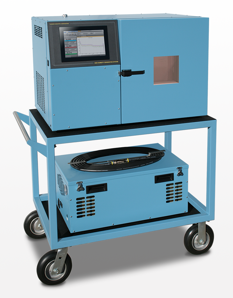
- High Flow Capability of 50 L/min
- Based on NIST Proven "Two-Pressure" Principle
- HumiCalc® with Uncertainty Mathematical Engine
- ControLog® Embedded Automation Software
- Generate: RH, DP, FP, PPM, Multipoint Profiles
- Externally Driven Chamber Fan
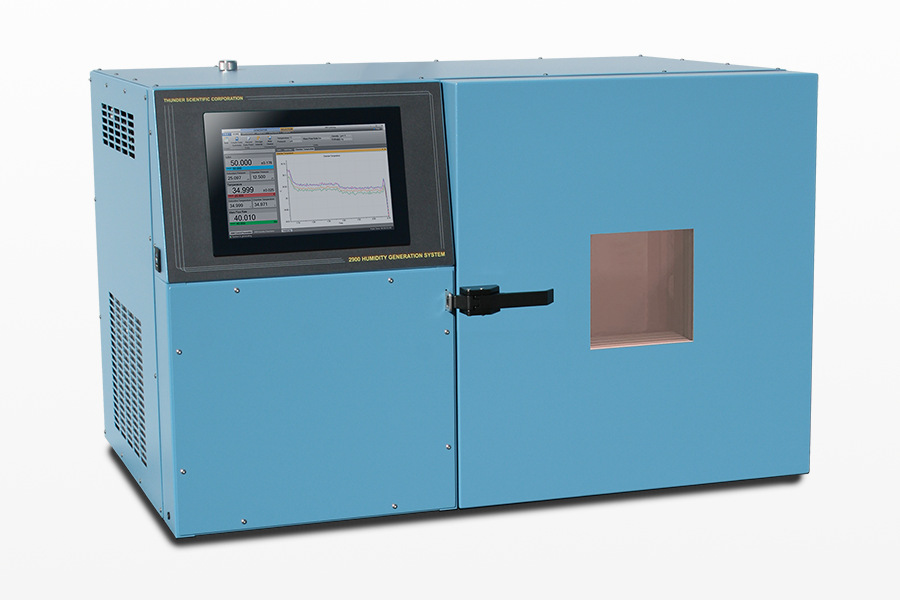
- 10.1" Multi-point Touch LCD
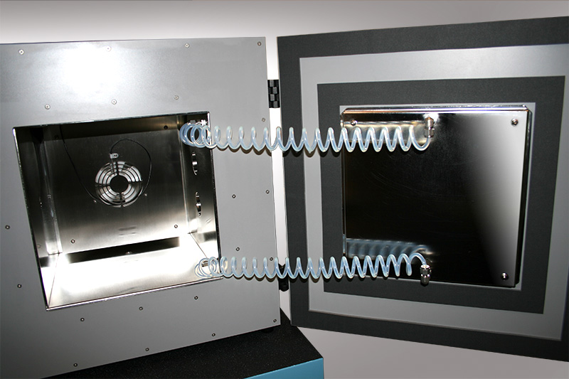 Fluid Jacketed Chamber Door
- Non-Windowed Door Standard
- Window Chamber Door Option Available
Get Software
1 Traceable to the International System of Units (SI) through a national metrology institute (NIST) recognized through a CIPM MRA.
6 Chamber pressure at 1 atmosphere, Uncertainty values represent an expanded uncertainty using a coverage factor, k=2, at an approximate level of confidence of 95%. Uncertainty is not specified at temperatures below 0 °C or at flow rates below 10 L/min. Uncertainty is based on the worst-case value from the 2900 uncertainty analysis.
SPECIFICATIONS
| Relative Humidity Range: | 10 to 95 %RH, 10 to 40 L/min |
| Relative Humidity Range: 2 | 95 to 98 %RH, 10 to 20 L/min |
| Frost Point Temperature Range: | –33.60 to 0 °C |
| Dew Point Temperature Range: | –36.94 to 70 °C |
| Chamber Fluid Temperature Range: 3 | –10 to 72 °C |
| Chamber Fluid Temperature Control Stability: 4 | 0.002 °C |
| Chamber Temperature Uniformity: 5 | < 0.04 °C |
| Chamber Fluid Temperature Heating Rate: from –10 to 72 °C | 0.5 °C per Minute (average) |
| Chamber Fluid Temperature Cooling Rate: from 72 to 0 °C | 0.5 °C per Minute (average) |
| Chamber Fluid Temperature Cooling Rate: from 0 to –10 °C | 0.2 °C per Minute (average) |
| Temperature Specification: | 0.027 °C |
| Gas Type: | Air or Nitrogen |
| Gas Pressure Rating: (MAWP) | 175 psiG |
| Gas Flow Rate Range: | 10 to 50 L/min |
| Gas Flow Rate Specification: | 5% of full scale |
| Saturation Pressure Range: | Ambient to 160 psiA |
| Saturation Pressure Specification: | 0.02% of full scale |
| Test Chamber Pressure Range: | Ambient |
| Supply Pressure Range: | Ambient to 150 psiG |
| Supply Pressure Specification: | ±1 psiG |
| Display Resolution: | 0.001 |
| Test Chamber Dimensions: | 12" H x 12" W x 10" D (30.48 cm x 30.48 cm x 25.4 cm) |
| Physical Dimensions: | 22" H x 36" W x 23" D (55.88 cm x 91.44 cm x 58.42 cm) |
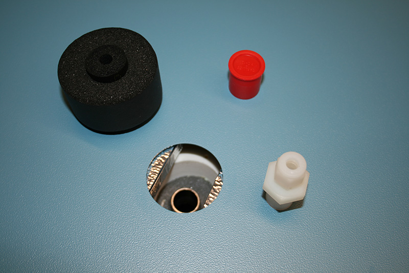
| Access Port: | 2 @ Ø1.875" (47.6 mm) located on right side |
UNCERTAINTY 6
| RH Uncertainty: 10 to 95 %RH, 0 to 70 °C, 10 to 40 L/min | 0.5% of reading |
| RH Uncertainty: 95 to 98 %RH, 0 to 70 °C, 10 to 20 L/min | 0.5% of reading |
| Dew/Frost Point Uncertainty: < 0 °C, 10 to 40 L/min | 0.05 °C |
| Dew Point Uncertainty: 0 to 70 °C, 10 to 40 L/min | 0.08 °C |
| Test Chamber Temperature Uncertainty: -10 to 72 °C | 0.031 °C |
| Test Chamber Pressure Uncertainty: Ambient | 0.007 psiA |
2 The system will limit mass flow rate to 20 L/min for %RH greater than 95.
3 Only the glycol/water heat transfer fluid circulating around the chamber is controlled to setpoint via the saturation temperature probe. Chamber temperature inside the chamber may vary depending on door configuration, setup, and uniformity. Note: the 2900 can only operate for a finite amount of time at or below 0 °C.
4 Temperature Control Stability is defined as the standard deviation over a 10-minute period, as measured by the saturation temperature control sensor after being at point for 60 minutes.
5 Chamber Temperature Uniformity is defined as the maximum temperature difference between any two locations at a single point in time. Locations are within one inch of the chamber wall and within 2.5 inches of the chamber door. Using a minimum chamber fan speed of 25% for a temperature range of –10 °C to 72 °C when using fluid jacket door option and ±10 °C from ambient when not.
6 Chamber pressure at 1 atmosphere, Uncertainty values represent an expanded uncertainty using a coverage factor, k=2, at an approximate level of confidence of 95%. Uncertainty is not specified at temperatures below 0 °C or at flow rates below 10 L/min. Uncertainty is based on the worst-case value from the 2900 uncertainty analysis.
UTILITIES
| Electrical Power: | 200-230/210-240 V~, 10 A, 1 Ø, 50/60 Hz |
| Gas Supply: | 175 psiG @ 50 L/min |
ENVIRONMENTAL
| Operating Temperature: | 15 to 30 °C |
| Storage Temperature: | 0 to 50 °C |
| Humidity: | 5 to 95% Non-condensing |
PRINCIPLE OF OPERATION
The “two-pressure” humidity generation process involves saturating air or nitrogen with water vapor at a known temperature and pressure. The saturated high-pressure air flows from the saturator, through a pressure reducing valve, where the air is isothermally reduced to test pressure at test temperature. Humidity generation is dependent on the measurement of temperature and pressure, not on the amount of water vapor measured in the air. System uncertainty is determined by the temperature and pressure uncertainties, and on the stability and uniformity of the measurements. When setpoint equilibration has been reached, the indication of saturation temperature, saturation pressure, test temperature, and test pressure, are used in the determination of all hygrometric parameters.

Elemental Schematic of the 2900 generator.
COMPUTER CONTROL
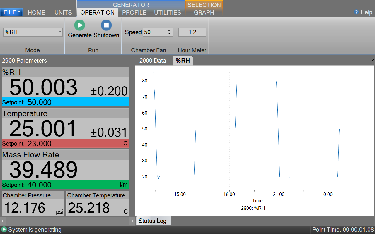
2900 Main Computer Screen
Control / Display Screen
The 2900 Humidity Generation System encompasses a high-performance stand-alone Control System that performs all functions required for humidity generation and control. The Control System employs 24 bit I/O modules with integrated signal conditioning to acquire data and uses serial interfaces to transducers and stepper motors to control the operation of generating humidity. The Control System utilizes an embedded operating system in conjunction with specialty software to control and interface with the human to machine interface (HMI) computer that runs ControLog®. ControLog is an embedded software application that fully automates the operation of the 2900 Humidity Generation System and allows various device connections through a number of different interfaces. ControLog uses Thunder Scientific’s HumiCalc® with Uncertainty as its mathematical engine for computing all humidity values and real-time uncertainties. Data from the generator and attached devices is automatically retrieved and stored for viewing in either numerical or graphical format in real time or post process. Data can be transferred off the system via a USB drive for further viewing, post processing and printing using an external Windows PC. The ControLog software also provides the primary interface to the operator via the multi-point touch LCD which allows the user to select humidity parameters, pressure, temperature, and flow units. The Parameter Tab is the primary interface for the user and is divided in two sections, Control and Calculated Humidity. Within each tab there are two different tiles, the Setpoint Tile is for the user to enter the desired setpoints and a Value Tile displays the Actual Value.
Temperature Calibration Screen
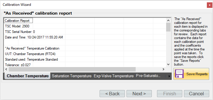
Temperature Calibration Coefficients Screen
Temperature Control: The 2900 humidity generation system incorporates a water/glycol jacked test chamber for extremely stable temperature control. Chamber temperature from -10 °C to 72 °C is controlled using PID (proportional-integral-derivative) algorithms to control the temperature of the water/glycol that jackets the test chamber and associated components. The water/glycol is circulated at the rate of approximately 14 gallons per minute by a magnetically coupled centrifugal pump providing the temperature conditioning of these components, resulting in excellent stability and uniformity for stable humidity generation.
Pressure And Flow Control: Pressure control and mass flow control are accomplished through computer actuation of electromechanical valve assemblies. Saturation pressure and mass flow are measured continuously and controlled using PID algorithms similar to those employed in temperature control.
Calibration: Proper calibration of the temperature and pressure transducers ultimately determines the accuracy of the generator. The humidity generator employs an integrated software calibration scheme allowing the 2900’s probes and transducers to be calibrated while they are electrically connected to the humidity generator. Coefficients for each transducer are calculated by the computer and stored to memory.
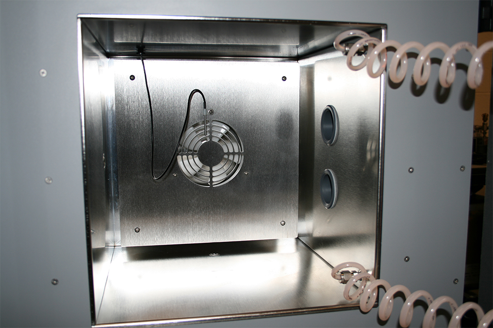
2900 Test Chamber
The 2900 humidity generating system incorporates a test chamber, with internal dimensions of 12" x 12" x 10". Test chamber pressure range is ambient. Access is available through 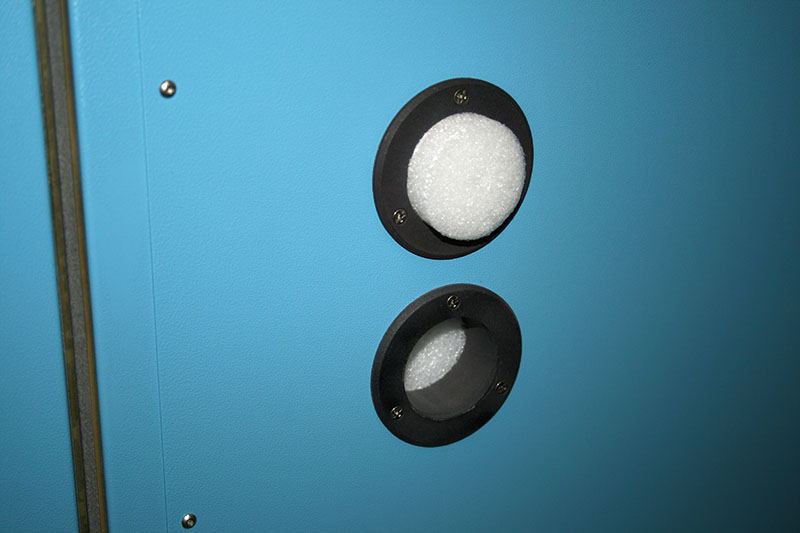 two 1.88" (47.7 mm) diameter ports located on the right side. An externally driven, variable speed, chamber fan is incorporated into the rear wall of the test chamber to reduce thermal gradients. While at the front of the test chamber the system comes equipped with a
  Fluid Jacketed Chamber Door, which helps to improve chamber uniformity. The test chamber accommodates various solid-state sensors, sensing systems, chilled mirror hygrometers, as well as material samples for environmental testing. Virtually any humidity and temperature may be generated within the operational limits of the generator. The output or recording of the device under test may then be compared with the generator’s data for analysis.
APPLICATIONS
Humidity Sensors and Chart Recorders: Insert humidity probes through a test port in the chamber or install the sensing systems into the chamber to: determine humidity calibration accuracy and/or characterize humidity sensitivity by subjecting the humidity sensor to a variety of humidity levels; perform operational checks such as the sensing systems capability to correctly calculate and display other humidity parameters; determine the repeatability, stability, hysteresis, and drift characteristics of various humidity sensing systems.
Chilled Mirror Hygrometers: Install the actual chilled mirror head into the chamber or insert a sample tube through the test port and draw a sample through the chilled mirror head to: verify mirror temperature measurement calibration when the hygrometer is in thermal equilibrium with its environment; perform operational checks of the heat pump and optical components before and after mirror cleaning and balancing; determine whether the hygrometer is controlling the mirror deposit in the liquid phase or ice phase when operating at dew and frost points below 0 °C; determine if the hygrometer is correctly calculating other humidity parameters; determine hygrometer’s repeatability, stability, and drift characteristics.
Environmental Testing: The 2900 can serve as a test bed for evaluation and R&D of humidity sensors, humidity sensing systems, and humidity sensitive products, e.g., polymers, composites, film, magnetic medium, pharmaceuticals, soil hydrology, consumables, electronics, optics, etc.
REFERENCE DOCUMENTS
Model 2900 Humidity Generation System Documents
Series 2900 operation and maintenance manual for the automated two-pressure humidity generator.
Supplementary Documents for This System.
Model 2900 Uncertainty Analysis
This document describes a complete uncertainty analysis of the Model 2900 in accordance with NIST Technical Note 1297. Each error source is identified, quantified, and combined to form an expanded uncertainty using a coverage factor, k=2, at an approximate level of confidence of 95%.
 Fluid Jacketed Chamber Door