FEATURES
- 0.5 %RH Uncertainty 1
- Traceable to SI 3
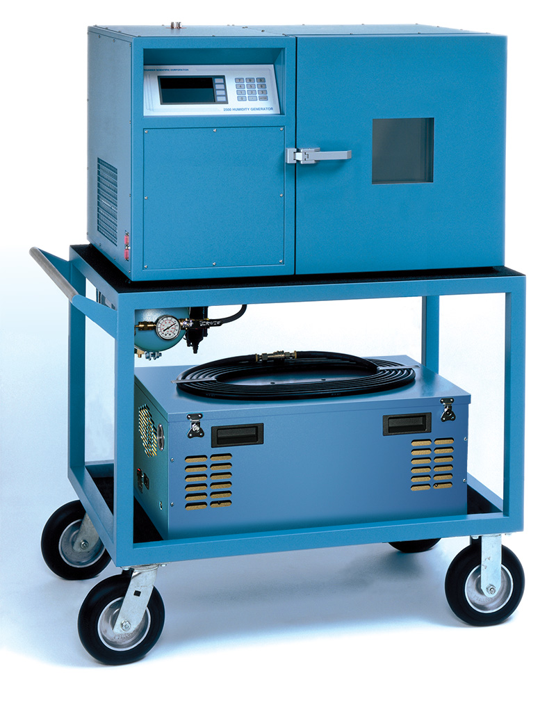
- Self Contained and Mobile
- Automated Control of User Setpoints
- 2500 ControLog® Automation Software
- HumiCalc® with Uncertainty Software
- Computerized Internal Transducer Calibration
- RS-232C Serial Interface
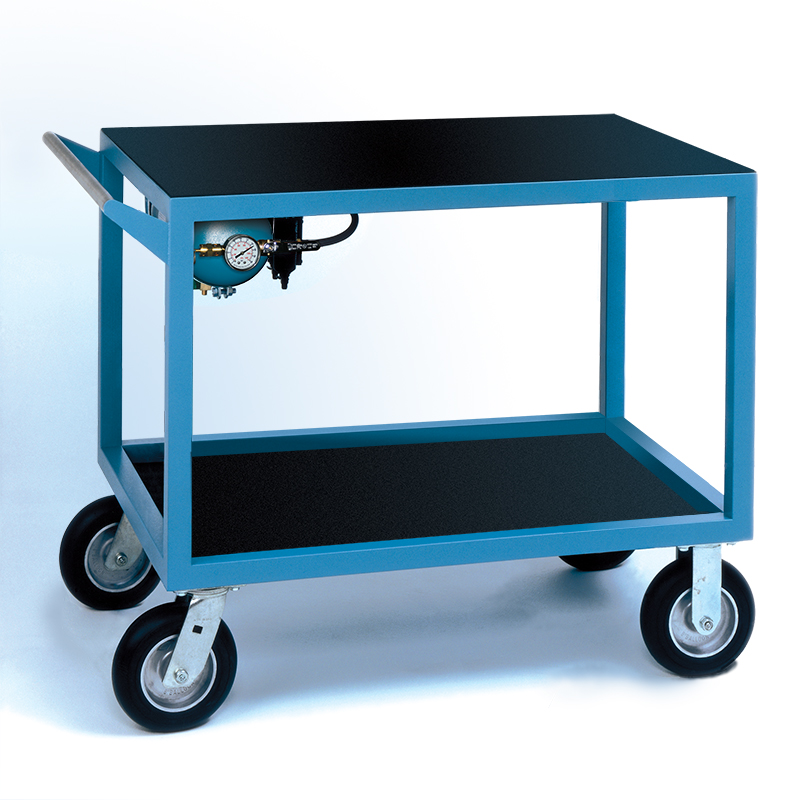
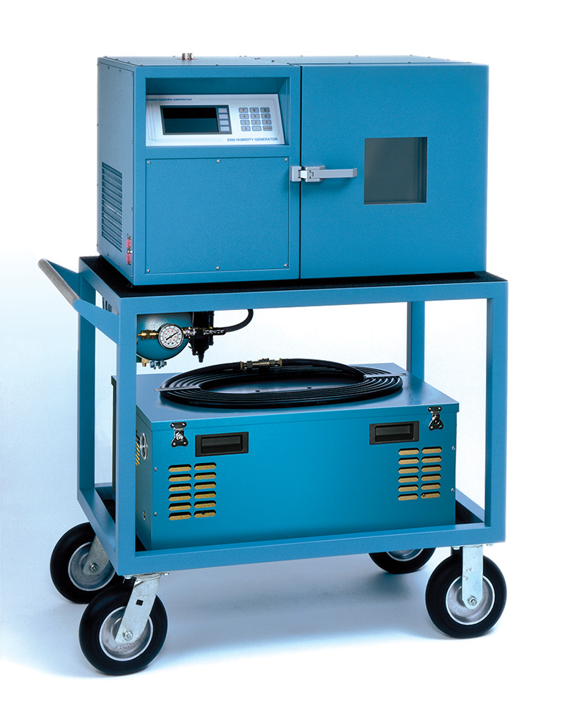
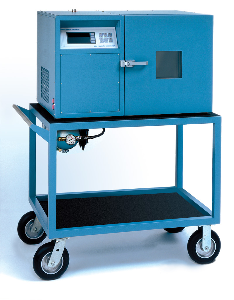
- 2500ST Mobile Cart with an Air Tank, Air Filters and Regulator Assembly
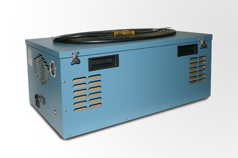
- Low Noise Air Compressor with Air Dryer (Option)
Get Software
1 Uncertainty values represent an expanded uncertainty using a coverage factor, k=2, at an approximate level of confidence of 95%. Uncertainty is not specified at temperatures below 0 °C or at flow rates below 10 L/min.
3 Traceable to the International System of Units (SI) through a national metrology institute (NIST) recognized through a CIPM MRA.
SPECIFICATIONS
| Relative Humidity Range: | 10 to 95 %RH |
| Relative Humidity Uncertainty: @ P c T c 1 | 0.5 %RH |
| Chamber Fluid Temperature Range: | 0 to 70 ºC |
| Chamber Fluid Temperature Range: (Optional) | –10 to 70 ºC |
| Chamber Temperature Uniformity: 2 | ±0.1 ºC |
| Chamber/Saturation Temperature Uncertainty: 1 | 0.06 ºC |
| Pre-Saturator/Expansion Valve Temperature Uncertainty: 1 | 0.20 ºC |
| Chamber Pressure Uncertainty: 1 | 0.15% FS |
| Chamber Pressure Range: | Ambient |
| Display Resolution: | 0.01 |
| Gas Flow Rate Range: | 5 to 20 L/min |
| Gas Flow Rate Resolution: | 0.02 L/min |
| Gas Flow Rate Uncertainty: 1 | 2% FS |
| Gas Type: | Air or Nitrogen |
| Gas Pressure Rating (MAWP): | 175 psiG |
| Heating: | Stainless Steel Immersion Heater |
| Heating/Cooling Rate: | 2.5 Minutes Per ºC Average |
| Cooling: | 1/3 hp R-134A Refrigeration System |
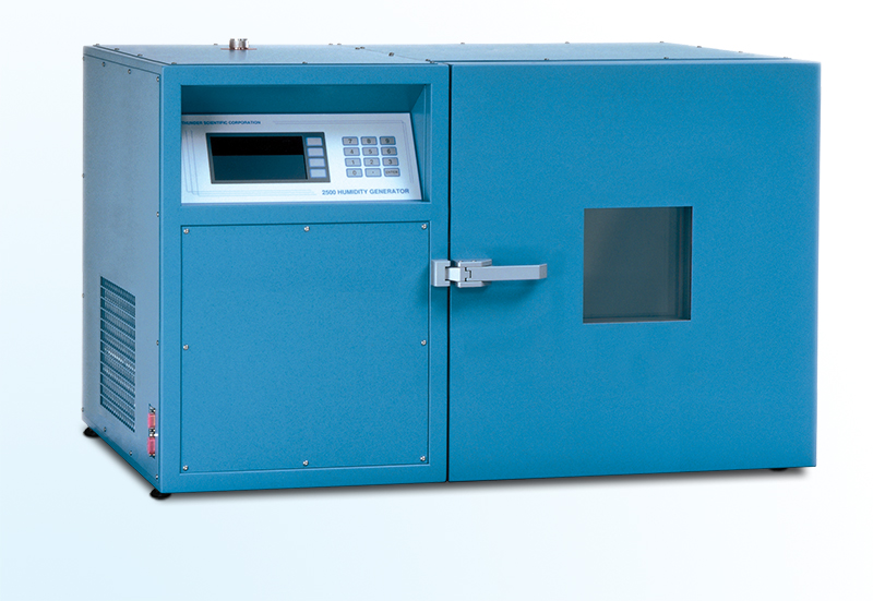
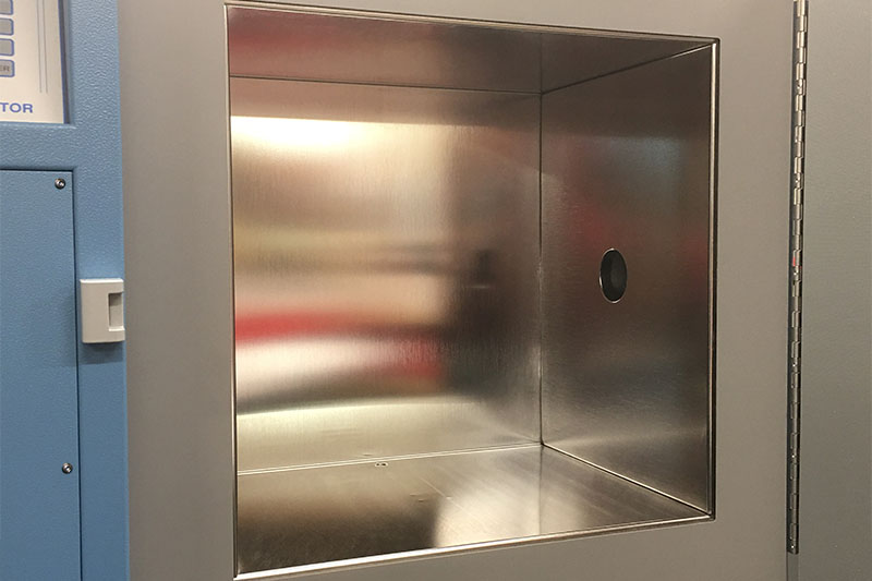
| Chamber Window: | 6" H x 6" W (152 mm x 152 mm) |
| Chamber Dimensions: | 15" H x 15" W x 12" D (38.1 cm x 38.1 cm x 30.5 cm) |
| Physical Dimensions: | 22" H x 36" W x 23" D (55.8 cm x 91.4 cm x 58.4 cm) |
| Physical Dimensions of Cart: | 33.25" H x 43" W x 26" D (84.5 cm x 109.2 cm x 66.0 cm) |
| Physical Dimensions 2500 with Cart: | 56" H x 43" W x 26" D (142 cm x 109 cm x 66 cm) |
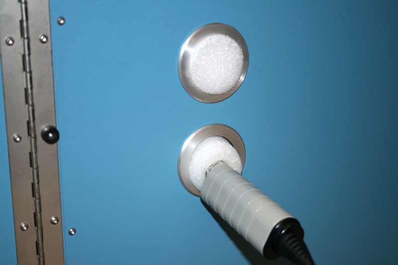
| Access Port: | SEE TABLE A |
1 Represents an expanded uncertainty using a coverage factor, k=2, at an approximate level of confidence of 95%. Uncertainty for relative humidity is not specified below 0 °C.
2 When operated at temperatures within 10 °C of room ambient temperature.
3 Traceable to the International System of Units (SI) through the National Institute of Standards and Technology (NIST) recognized through CIPM MRA.
UTILITIES
| Electrical Power For ST Model: | 210-240 V~, 8 A, 60 Hz |
| Electrical Power For ST Model: (Optional) | 200-230 V~, 8 A, 50 Hz |
| Air Compressor: | 100-120 V~, 10 A, 50/60 Hz |
| Air Compressor: (Optional) | 220-240 V~, 6.3 A, 50/60 Hz |
| Air Supply (External): | Clean Oil Free Instrument Air @ 175 psiG & 20 L/min |
ENVIRONMENTAL
| Operating Temperature: | 15 to 30 ºC |
| Storage Temperature: | 0 to 50 ºC |
| Humidity: | 5 to 95% Non-condensing |
| TABLE A |
| Access Port Dimensions |
| Option | # Ports | Port Diameter | Location |
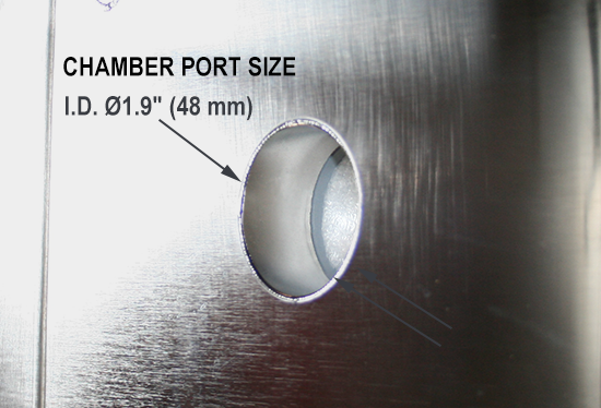
| Standard | 1 | 1.9" (48 mm) | Right Side |
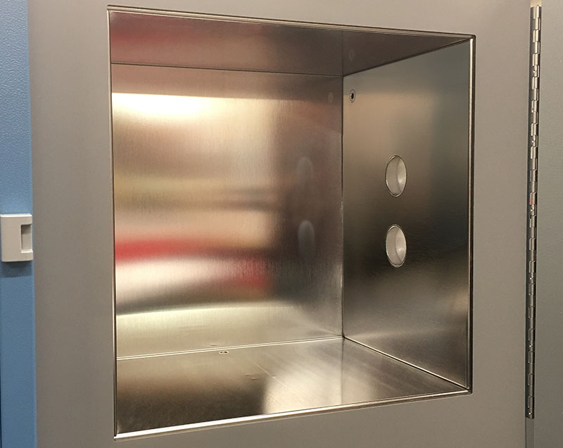
-TPA | 2 | 1.9" (48 mm) | Right Side |
| 1 | 1/4" Swagelok® | Right Side |
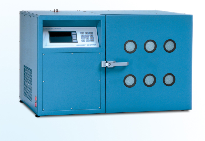
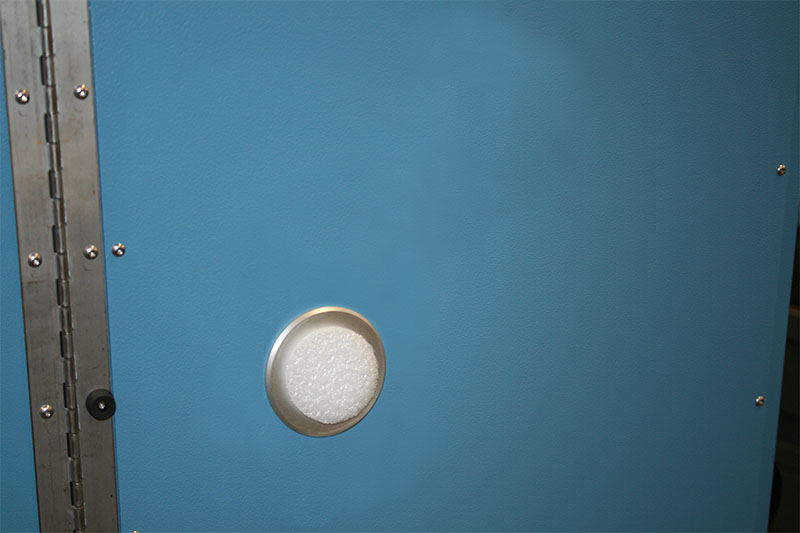
| -LPD | 6 | 1.93" (49 mm) | In Door |
PRINCIPLE OF OPERATION
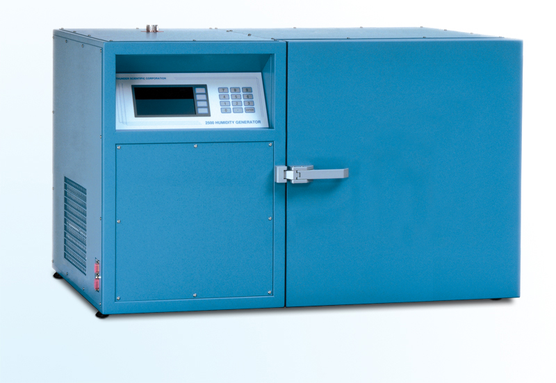
The Model 2500 Benchtop Humidity Generator operates using an on board multifunction CPU in conjunction with other peripheral cards to perform calculation and control functions. The embedded computer control system allows the 2500 to generate known humidity levels unattended, freeing the operating technician from the task of system monitoring and adjustment. A computer and/or printer may be connected via the bi-directional RS-232C interface ports allowing remote setpoint control and continuous acquisition of system data. Humidity and temperature setpoint values are input by the operator from the front panel keypad while visual indications of system status are displayed in real time on the liquid crystal display.
COMPUTER CONTROL
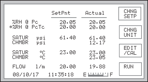
2500 Control Display Screen
Control / Display Screen
All control and measurement parameters critical to the operation of the humidity generator are displayed on this screen. Each parameter in the left most column is identified with a brief title and corresponding units. The generator operates in a variety of user selectable pressure, temperature, and flow units. Some of these are °C, °F, psi, "Hg, Tor, mbar, kPa, L/min, l/h, cfm and cfh. Humidity is calculated and displayed in percent relative humidity (%RH). The asterisk in the left most column indicates the active humidity control parameter. The "SetPnt" column lists control setpoints and the "Actual" column lists all of the measured data and calculated parameters of the generator.
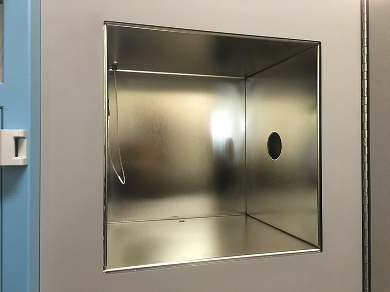
2500 Test Chamber
The system utilizes a fluid jacketed test chamber for extremely stable temperature control. Temperature setpoint control is attained by controlling the temperature of the circulating fluid medium that jackets the test chamber and associated humidity generation components. Chamber and saturation temperatures are governed by this medium and are digitally controlled by the computer at any value between 0 °C and 70 °C using PID (proportional-integral-derivative) algorithms.
Calibration / Display Screen
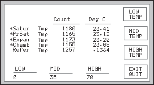
Calibration display screen
Calibration: The 2500 humidity generator employs an integral programmatic calibration scheme allowing the temperature and pressure transducers to be calibrated while they are electrically connected to the humidity generator.
Coefficients for each transducer are calculated by the computer and stored in the system’s nonvolatile memory until the next calibration is performed.
Pressure And Flow Control: Pressure control and mass flow control are accomplished through computer actuation of electromechanical valve assemblies. Pressure and flow are measured continuously and controlled using PID algorithms similar to those employed in temperature control.

Elemental Schematic of the 2500 generator.
APPLICATIONS
The fluid jacketed test chamber can accommodate humidity sensors, hygrothermographs, chilled mirror hygrometers, and various material samples for environmental testing. Virtually any humidity and temperature point may be generated, for any length of time, within the operational limits of the generator. The output of the device under test may then be compared with the generator's printed data for analysis.
Humidity Sensors And Chart Recorders: Insert humidity probes through the two inch port in the side of the chamber or place hygrothermographs into the chamber and you can: determine humidity calibration accuracy and characterize humidity sensitivity by subjecting the sensing system to a variety of humidity levels; perform operational checks such as the sensing systems capability to correctly calculate and display other humidity parameters; determine the repeatability, stability, hysteresis, and drift characteristics of various humidity sensing systems.
Chilled Mirror Hygrometers: Install the actual chilled mirror head into the chamber or insert a sample tube through the test port and draw a sample through the chilled mirror head and you can: verify mirror temperature measurement accuracy (calibration) when the
hygrometer is in thermal equilibrium with its environment; perform operational checks of the heat pump and optical components before and after mirror cleaning and balancing; determine whether the hygrometer is controlling the mirror deposit in the liquid phase or ice phase when operating at dew and frost points below 0 °C; determine if the hygrometer is correctly calculating other humidity parameters; determine the hygrometer's repeatability, stability, and drift characteristics.
Environmental Testing: The 2500 can serve as a test bed for evaluation and R&D of humidity sensors, humidity sensing systems, and humidity sensitive products, e.g., polymers, composites, film, magnetic medium, blood gas analysis, pharmaceuticals, soil hydrology, consumables, electronics, optics, etc. Depending on the temperature and humidity being generated, the 2500 may operate continuously from hours to months. With continuous generation of a nominal 50 %RH at 21 °C, the reservoir will last about two weeks between refills.
REFERENCE DOCUMENTS
Model 2500 Humidity Generation System Documents
Series 2500 operation and maintenance manual and spec sheet for the two-pressure humidity generator.
Model 2500 Uncertainty Analysis
This document describes a complete uncertainty analysis of the Model 2500 in accordance with NIST Technical Note 1297. Each error source is identified, quantified, and combined to form an expanded uncertainty using a coverage factor, k=2, at an approximate level of confidence of 95%.





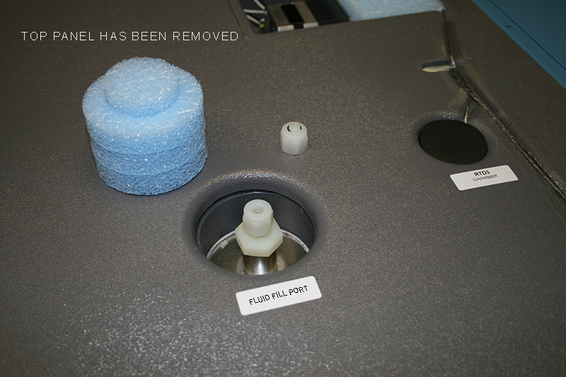
 Low Temperature Option